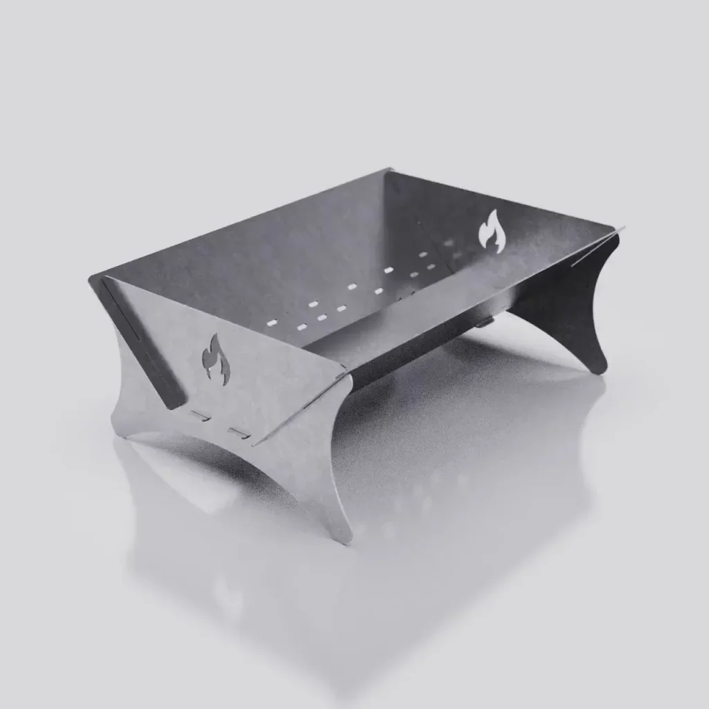
DXF Files Optimized for Plasma Cutting and CNC Machining
In modern manufacturing and design, computer-aided manufacturing (CAM) technologies such as CNC (computer numerical control) and plasma cutting have revolutionized production capabilities. The use of automated cutting tools has not only improved precision, but also expanded the range of materials and shapes that manufacturers can work with. At the heart of many CNC and plasma cutting projects is the Drawing Exchange Format (DXF) file, which serves as a digital blueprint for cutting, engraving and shaping designs. Understanding how to optimize DXF files specifically for these processes is essential to maximizing accuracy, efficiency and quality in manufacturing.
Why Optimized DXF for CNC and Plasma Cutting Matters
When creating or modifying a DXF file for CNC or plasma cutting, optimization is critical for several reasons. Optimized DXF files ensure efficient toolpaths, reduce waste, and improve the overall quality of the final product. A well-optimized file also reduces production time and minimizes machine wear, which is critical to extending equipment life and lowering operating costs. Conversely, poorly optimized files can result in unnecessary machine movements, incorrect cuts, or even damage to the material or machine.
Optimized DXF for CNC and Plasma Cutting refers to files that have been prepared with these processes in mind. This includes cleaning up geometry, adjusting line segments, ensuring closed paths where necessary, and adapting the design to the technical requirements of the specific machine to be used. When done correctly, these adjustments can make a significant difference in speed, accuracy and material utilization.

Key considerations when optimizing DXF files
- Simplify Geometry Complex geometries with excessive nodes or detail can slow down CNC and plasma cutters and increase the likelihood of errors. Simplifying the design by reducing unnecessary nodes and redundant elements ensures a smoother cutting process. For example, curves can be replaced with straight lines or fewer points when high detail is not critical. Simplifying shapes also reduces the data size of the DXF file, making it easier for machines to process quickly.
- Ensure Closed Paths CNC and plasma cutters typically require closed paths to perform cuts correctly. Open paths can result in incomplete cuts, errors, or deviations from the intended design. By ensuring that all shapes and contours in the DXF file are closed, designers can improve cutting accuracy and eliminate potential problems in the final product.
- Eliminate Overlapping and Duplicate Lines Overlapping and duplicate lines in DXF files can cause machines to make redundant cuts, resulting in excessive wear on cutting tools and wasted time. During the optimization process, it is important to check for and remove any overlapping lines. This step not only reduces the workload on the machine, but also minimizes the risk of damage to the material due to repeated cuts in the same location.
- Setting Line Widths Appropriately Line width settings in DXF files play an important role in CNC and plasma cutting processes. A line width that is too thin or too thick can result in incorrect cuts because machines may interpret them differently. Using a standardized line width that matches the machine’s requirements will ensure that the machine reads the design as intended. It is recommended that you consult the machine’s specifications for guidance on ideal linewidth parameters.
- Set Tolerance Levels for Precision Various materials and machines may require specific tolerance levels to achieve optimal cuts. Tolerance settings determine how closely the machine will follow the DXF geometry, which is especially important for intricate designs or when working with materials that tend to warp or heat distort (in the case of plasma cutting). Adjusting tolerance levels helps maintain design fidelity and can prevent problems such as rough edges or inaccurate dimensions in the final product.
- Optimize Tool Paths The efficiency of a CNC or plasma cutting operation is greatly influenced by the tool path – the route the machine takes to cut out the design. Efficient toolpaths reduce production time, minimize material waste and limit the amount of time the cutting tool is in use. Optimizing the DXF file for the shortest and most efficient toolpath can improve the speed and cost-effectiveness of the production process.
- Organize Layers Using layers within a DXF file provides greater control and flexibility during the cutting process. Each layer can represent a different operation or tool setting, such as cutting, engraving or scoring. By organizing the file into layers, operators can easily adjust settings for specific parts of the design, improving accuracy and ensuring that each section is treated appropriately.
Preparing DXF Files for Plasma Cutting
Plasma cutting is a process that uses an accelerated jet of hot plasma to cut conductive materials such as steel, aluminum, brass and copper. Unlike CNC routing, which uses a physical cutting tool, plasma cutting relies on heat and gas to achieve the desired cuts. Therefore, optimizing DXF files for plasma cutting requires consideration of factors such as material thickness, heat tolerance, and edge quality.

For plasma cutting applications, designers should consider using offset lines to account for the width of the plasma arc, which is wider than a typical cutting tool. They should also avoid intricate details and thin, delicate parts within the design, as these can be difficult for the plasma cutter to accurately reproduce. In addition, plasma cutting tends to create a heat-affected zone (HAZ) along the edges, so maintaining proper spacing between elements in the DXF file can help prevent unwanted melting or warping.
Software Tools for DXF File Optimization
Several software options are available to optimize DXF files specifically for CNC and plasma cutting, with features geared toward design simplification, path planning, and error correction. Programs such as AutoCAD, CorelDRAW, and Adobe Illustrator allow for extensive editing and can help optimize the file prior to exporting the DXF. For CNC-specific applications, software such as Fusion 360, Inkscape, and SheetCAM can handle toolpath optimization, node reduction, and layer management, making them suitable for both novice and advanced users.
Some software solutions offer automated tools for detecting open paths, removing duplicate lines, and adjusting tolerances, which can be especially helpful when preparing files for complex or large cutting operations. While manual adjustments are often required for fine-tuning, these software options greatly streamline the optimization process.
Conclusion
Optimizing DXF files for CNC and plasma cutting is a critical step in any project involving these technologies. By taking the time to carefully prepare the DXF file, manufacturers and designers can ensure smoother machine operation, reduce production time, and improve the quality of the final product. With the right combination of file simplification, closed path verification, toolpath optimization and layer organization, a DXF file can be transformed into a highly efficient blueprint for automated cutting processes.
In a rapidly evolving field like CAM, staying on top of file optimization best practices can make a significant difference in productivity and profitability. The journey from digital design to physical object begins with a well-prepared DXF file, making it an essential foundation for successful CNC and plasma cutting projects.


